


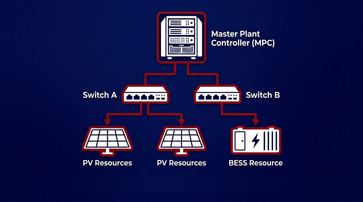
Anyone involved in utility-scale power plants is already aware that the controllers are the heart of the control system. Stop the heart, and everything else stops with it. At Nor-Cal Controls, we know that in a power plant, that kind of downtime trips the site, creates instability in the grid, and even triggers costly performance penalties depending on the contract.
This post is about redundant controllers, specifically focusing on what they do, why they matter, and how it all plays out in systems running both Plant Power Controllers (PPCs) and Master Power Controllers (MPCs). When designing controls for a new plant or retrofitting an old one, redundancy control is a must-have feature these days.
Quick refreshers
The Power Plant Controller (PPC) operates at the resource level (PV or BESS). It translates active and reactive power commands from the MPC to manage the inverters, while simultaneously handling grid code compliance duties like curtailment control, voltage regulation, and frequency response. Basically, it’s the plant manager talking to the grid operator and issuing instructions on the floor.
Master Plant Controller (MPC) comes into play in bigger or more complex setups with multiple resources, battery storage, and hybrid configurations. It sits above the PPCs and coordinates them. If the PPC is a plant manager, the MPC is more like the regional director overseeing several resources. Both become single points of failure if redundancy is skipped.
What does redundancy mean?
Redundancy means having a standby controller ready to take over the site instantly when the primary controller fails. For controllers, that means running a secondary device. In some cases, a tertiary unit is installed that mirrors the primary continuously and can step in with almost no disruption.
That’s a different thing from just having a spare sitting in a cabinet. A passive spare still needs someone to notice the failure, physically intervene, and bring it online, which is not as efficient as the site will be offline and may affect the grid. Real redundancy is active where the backup is live, synced, and ready to take over in milliseconds without creating oscillations at the point of interconnection (POI).
Three common architectures
- Hot Standby (Active-Passive) is the most common setup. One controller does the work; the other stays powered and feeds the same data in real time. The instant a fault is detected, the standby takes over, usually in a few seconds, depending on the device’s capability. The control returns to the primary controller automatically as soon as it is up and running.
- Active-Active (Load Sharing) has both controllers working at once, splitting the load. If one drops, the other picks up everything. We get better performance and redundancy together, but it demands tighter synchronization, so both units always hold identical states. In most controllers, a common issue we have observed is that when the primary controller returns to its normal state after a fault or failover, it does not automatically transition back to the active state.
- N+1 or N+M Redundancy fits very large plants with several PPCs or MPCs, which allows us to keep one spare for every N active controllers. It works well where a plant is split into multiple feeder zones, each with its own PPC, since a single spare can cover any zone that fails. It’s a way to get coverage without spending on 1:1 backup everywhere. This approach is not commonly used in the PV or BESS industry, as it requires significant programming effort since the spare controller would need to be configured to take over for a specific controller.
How this plays out differently for PPCs and MPCs
PPCs and MPCs don’t necessarily fail the same way, so redundancy must be deployed at each level in a power plant.
At the PPC level, the main issue is keeping grid compliance functions running without interruption. A PPC failure mid-operation can push the resource into an unstable state that leads to inverters tripping, disconnecting from the grid, or breaching voltage limits. To avoid that, we need continuous state sync between primary and standby (setpoints, measurements, comms status, all of it), a bump-less transfer so switchover doesn’t cause a sudden power jump, redundant comms paths to inverters and SCADA, and importantly, independent power supplies for each controller. Sharing one power feed between primary and backup defeats the whole point, so power redundancy needs to be planned as well.
MPC redundancy is more critical, since a failure here can knock out the entire plant at once, not just one zone. The backup MPC must know the live state of every PPC it supervises, and not a snapshot from a few minutes ago. Any lag there could create an unsafe window during failover.
If we are planning for an active-active MPC setup, we need a dedicated rule for which controller has final control over the PPC at any moment. Otherwise, we risk conflicting commands hitting the same PPC, leading to a major fault. Most engineers solve this with a heartbeat mechanism: the primary sends a steady signal to the secondary, and if it goes quiet past a set threshold, the secondary takes charge. Controllers such as SEL RTAC, Emerson PACSystems, and Allen-Bradley PLCs include built-in redundancy features that automatically detect controller failures and perform a seamless failover to the standby controller.
Failure scenarios worth knowing
Hardware failure is one common case. The watchdog timer catches the loss of response, and the standby steps in.
Network Failure between MPC and PPC (fiber cut, switch failure) can trigger the failover. Without redundancy, the PPC usually falls back to a hold-last-value or safe-state mode, which isn’t always right for dynamic grid conditions. Every controller has two Network Interface Cards (NICs), meaning they can have two IP addresses. Planning network redundancy goes hand in hand with controller redundancy. Connecting both active and passive controllers to a single switch will kill the purpose of the redundancy.
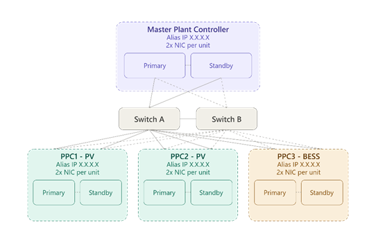
Figure: Sample MPC & PPC redundant architecture
A Power Failure in a control panel will force the active MPC and PPC to shut down. Most of the modern controllers offer dual power supply. Similar to network redundancy, power redundancy is essential to avoid a single point of failure.
The Logic Failure is difficult to detect. Without robust fail-safe logic to handle all edge cases, the active controller may continue sending erroneous values, preventing the standby controller from taking over.
Design Considerations
Things to consider while designing a redundant control system
- Switchover time is defined and validated (typically <1 s for hot standby, often 100–300 ms in practice) and confirms the chosen architecture meets it under load, not just on technical specifications.
- Independent power supplies and UPS feed for primary and standby.
- State synchronization tested under real load conditions. Setpoints, measurement buffers, and comms handshakes all need to match at switchover, not just static config.
- Redundant communication paths on both sides, such as upstream to HMI/Utility and downstream to inverters, typically on physically separate media, so a single cable fault doesn’t take out both links.
- Use an aliased (virtual) IP address for controller communications to provide a single communication endpoint and eliminate the need for multiple cross-connections.
- The redundancy architecture depends on the controller manufacturer and its communication capabilities. For example, some controllers do not support DNP3 or Modbus communications over a redundant (virtual) IP address, which can influence the overall redundancy design.
- Failover tested under actual operating conditions, during high-irradiance periods, and active reactive power dispatch.
- Alarm and notification logic that confirms both events, like “primary failure detected AND standby successfully in control”.
Where This Leaves Us
Redundant controllers are no longer a luxury as they’re a necessity for modern PV and BESS systems. As power plants are expected to provide ancillary services, respond to real-time grid events, and maintain voltage at the point of interconnection, the PPC and MPC can no longer be single points of failure. A reliable redundancy design starts with proper state synchronization, independent power supplies, redundant communication paths, and solid failover testing. Investing in redundancy upfront not only improves reliability and availability but also provides confidence that the control system will always be available and operating when it’s needed most.
Partner with the Experts
Ready to eliminate single points of failure at your facility? Contact Nor-Cal today to discuss how our engineering team can design, program, and commission a highly reliable, redundant PPC or MPC solution customized for your next utility-scale solar or storage project.